FPGA Based Theremin Project
The goal of this project is to provide open source DIY build of FPGA based digital Theremin
Unlike analog theremins, digital theremin is in general capacitive sensor which measures distance from hands to antennas, and digital synthesizer which generates sound.
Table of Contents
Existing digital theremins available
There is one well known digital theremin on market, Moog Theremini.

Due to high latency, it's mostrly unplayable, just a toy.
There is a good digital theremin project, Open.Theremin but it still uses too poor hardware (Arduino UNO) as a base.

Dewster's D-Lev FPGA theremin project is in development since 2012. Good FPGA based design, produces realistic sound without latency. Although, currently used hardware has not enough resources. Build project for this theremin with professionally made cabinet.
In this project, we will try to provide easy to build DIY theremin design with potentially unlimited capabilities.
Hardware
Choosing FPGA board and other third party hardware
Why FPGA?
- Allows to implement high precision very sensitive antenna capacity sensors - cannot be done with general purpose MCUs
- Wide range of audio DSP algorithms may be implemented in FPGA
- Low latency: FPGA is able to update pitch and volume for each audio sample
- Hardware acceleration of display is possible (e.g. update current note in on-screen tuner in realtime)
Why PSOC?
- PSOC FPGA development boards provide one or more ARM cores which may handle a lot of non-realtime functionality like GUI and reduce FPGA resources usage
- ARM hardware cores in PSOC provide better performance than softcores, and have hardware floating point support
- Rich GUI may be implemented using PSOC
- PSOC development boards have a lot of SDRAM which is needed, e.g. for reverberation effects
- Harware SDRAM controller with DMA support in PSOC - with softcore, you will spend a lot of resources for SDRAM controller even if board contains SDRAM
Why Xilinx
- The only choice is between Xilinx and Intel(Altera). Other vendors provide less mature tools, with lower functionality.
- I'm more familiar with Xilinx solutions
- Xilinx provides free license for bare metal programming of PSOC (Vivado WebPack). (AFAIK, there is no free license for bare-metal applications for Intel)
- Xilinx Series 7 devices have bigger LUTs, DSP modules, BRAMs
Digilent Cora Z7 board (either 7007 or 7010) is inexpensive solution which mets all hardware requirements for this project.
For audio playback / recording, we need some audio codec board(s). Digilent PMod I2S2 and AMP3 were selected.
It makes sense to add touch screen LCD for rich GUI functionality and advanced controls. Waveshare 4.3inch display was selected.
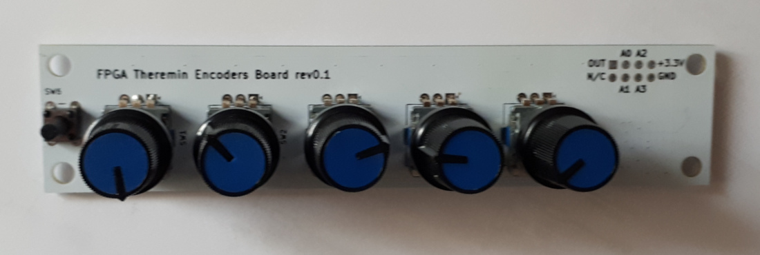
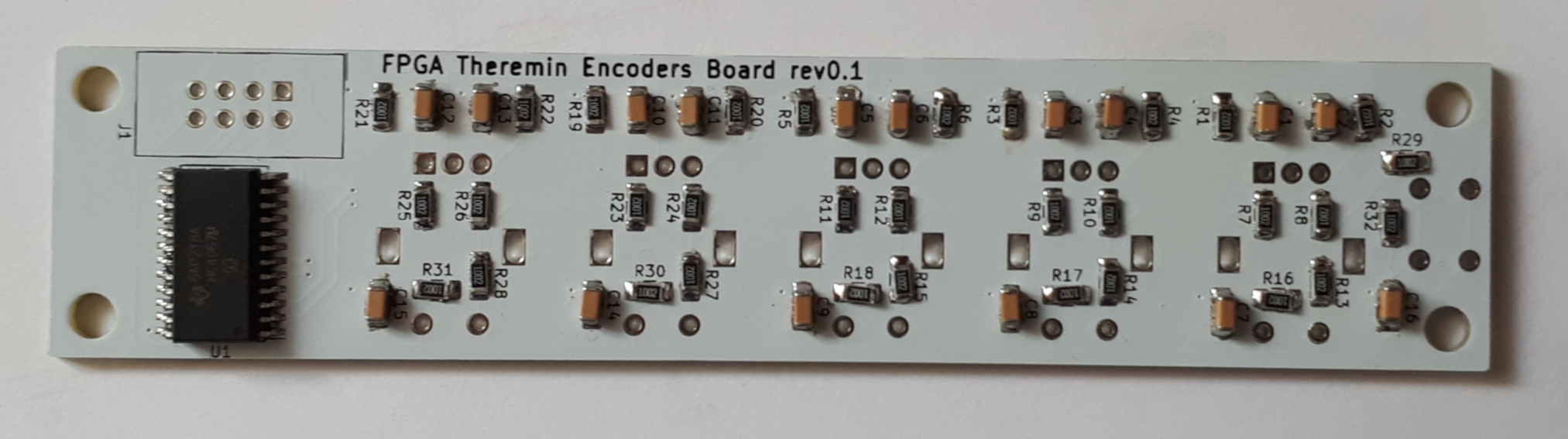
Even with touch screen, it makes sense to have hardware controls: encoders, buttons, pedals.
List of third party devices or boards needed for this design
| Device | Features | Store link | Datasheet |
|---|---|---|---|
Digilent Cora Z7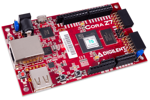 |
Xilinx Zynq 7007/7010 based development board The Digilent Cora Z7 is a ready-to-use, low-cost, and easily embeddable development platform designed around the powerful Zynq-7000 All-Programmable System-on-Chip (APSoC) from Xilinx. The Zynq-7000 architecture tightly integrates a single or dual core 667MHz ARM Cortex-A9 processor with a Xilinx 7-series FPGA. This pairing grants the ability to surround the processor with a unique set of software-defined peripherals and controllers, tailored for the target application. Arduino/chipkit shield connector and 2 Pmod connectors 512 MB DDR3 memory 17,600(14,400) LUTs, 35,200()28,800 Flip-flops, 270 KB(225 KB) block RAM |
Digilent store $99/$129 | Reference manual |
Digilent PMod I2S2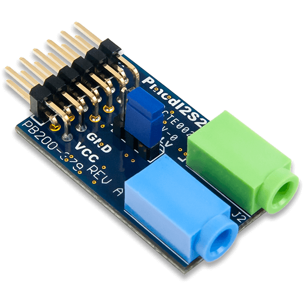 |
24bit I2S 48000Hz stereo Line In / Line Out | Digilent store $21.99 | Reference manual |
Digilent PMod AMP3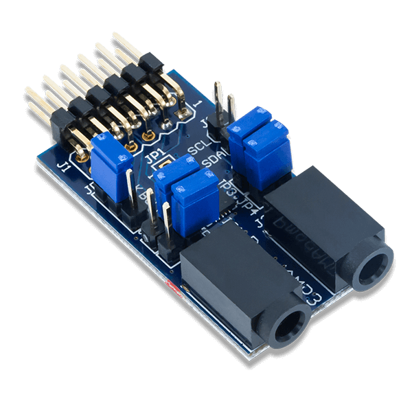 |
24bit I2S 48000Hz stereo Phones Amplifier | Digilent store $9.99 | Reference manual |
5V 2.5A Switching Power Supply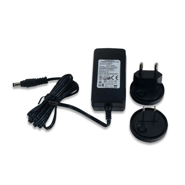 |
5V, 2.5A | Digilent store $12.99 | No reference manual |
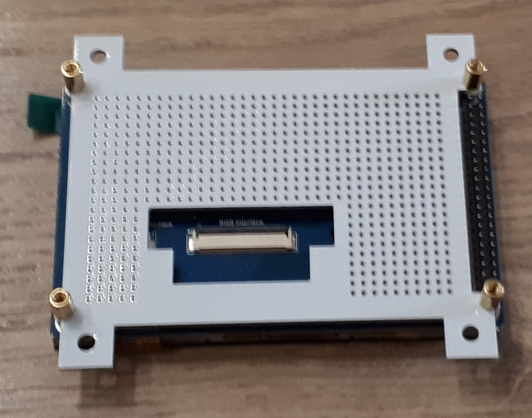
4.3inch Capacitive Touch LCD, 800x480 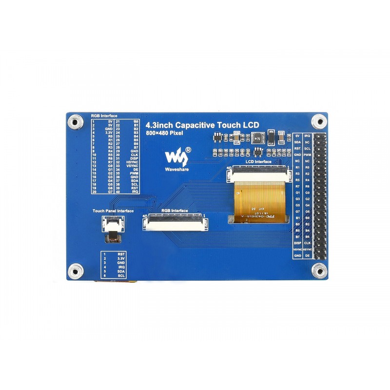 |
RGB interface 2x20 2.54mm pin header or FPC connector Touch screen controller accessible via I2C |
Waveshare store $27.99 | Wiki User manual |
Antennas and cabinet construction
Theremin cabinet and antennas may vary in wide range.
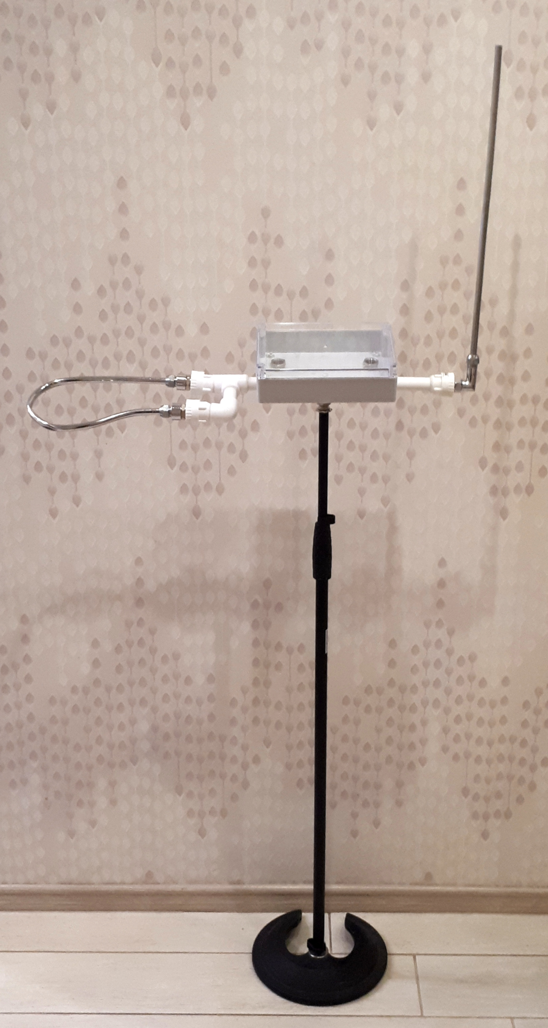
Proposed cabinet construction may be found on separate page.
All PCBs
| Board | KiCAD Schematic | Gerber file |
|---|---|---|
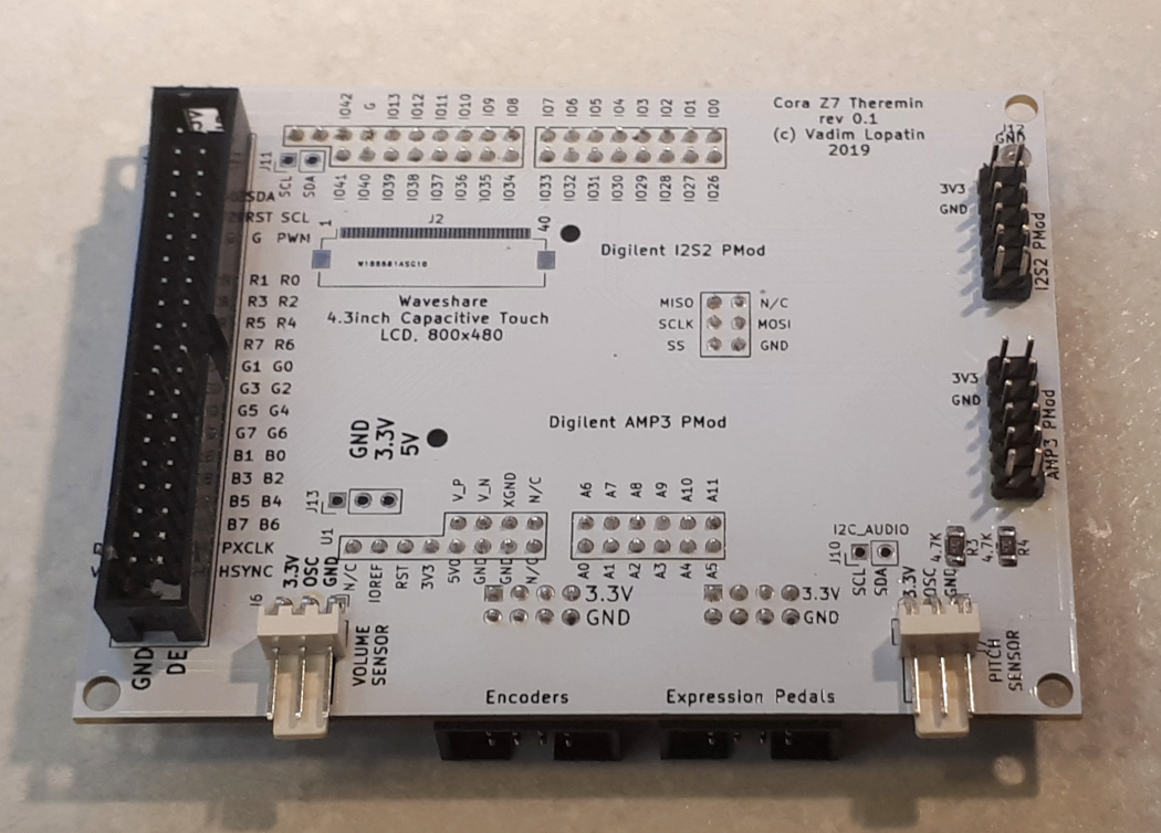
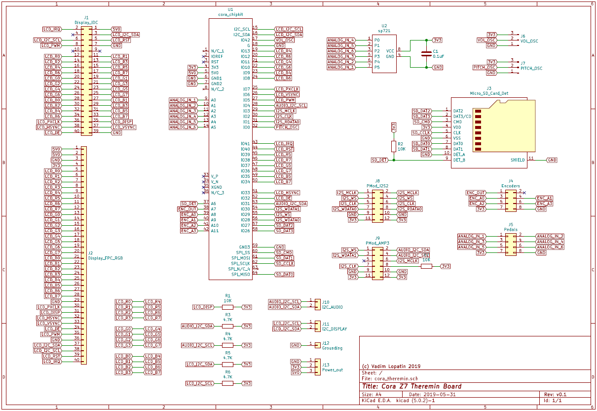
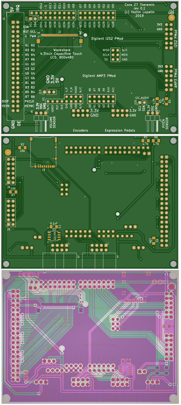
|
Connected to Cora Z7 board using Arduino/Chipkit connector. Two on-board PMods of Cora board are left unused for future extensions. Contains additional microSD card socket. Used to connect other boards
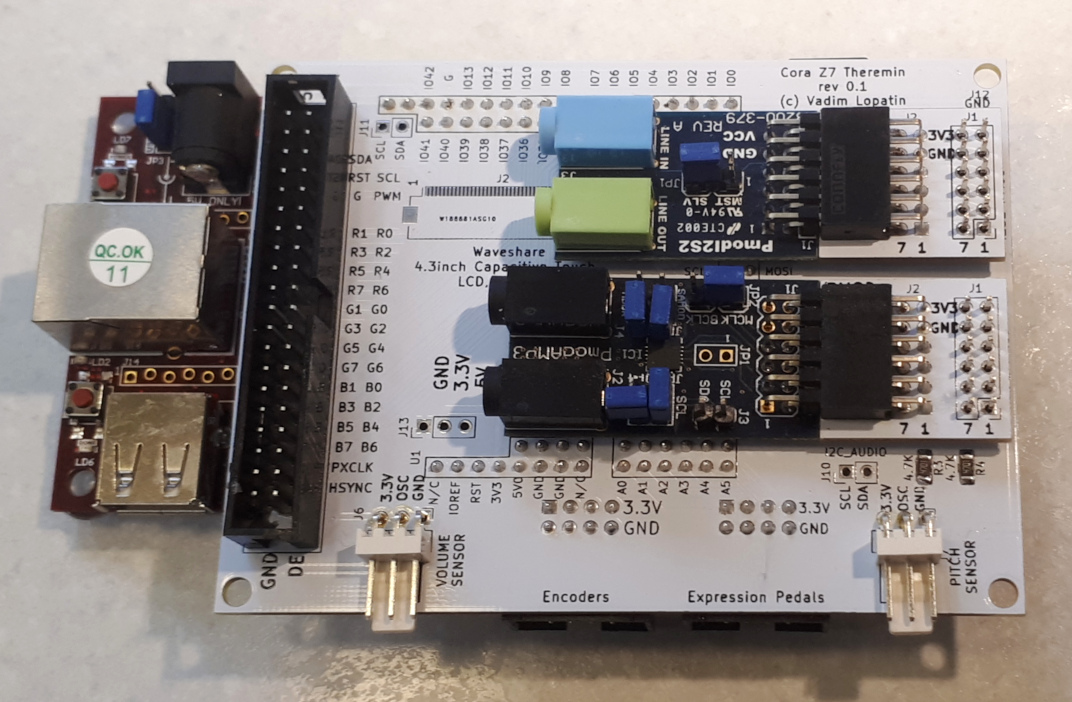
|
 |
|
|
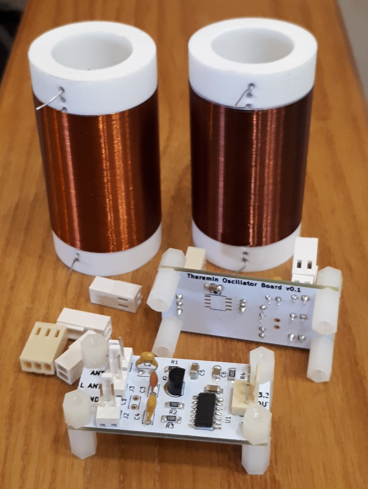
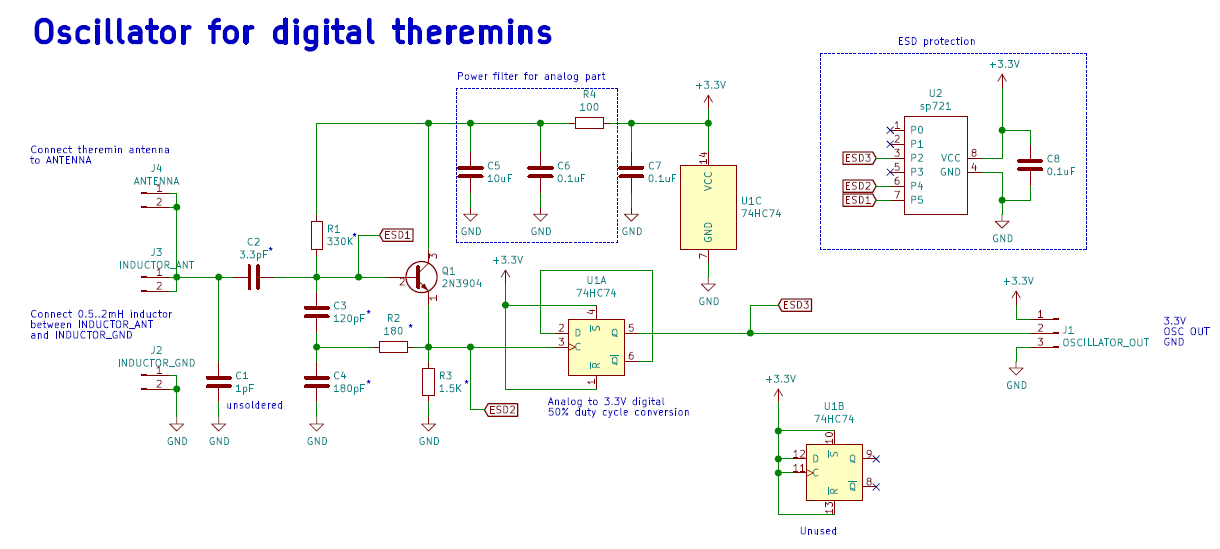
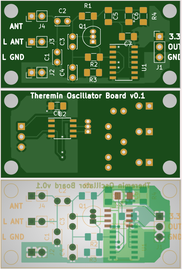
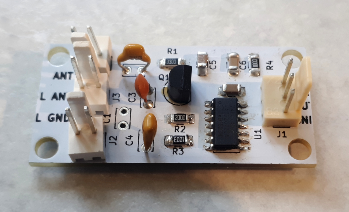
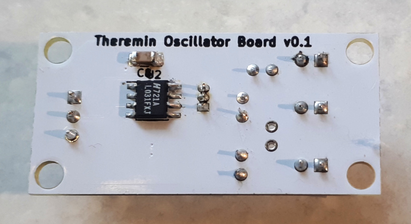
Two identical oscillator boards are needed for theremin: Pitch oscillator and Volume oscillator. Oscillator output is 3.3V digital signal with frequency which depends on coils (0.3..2MHz). Each oscillator requires air core inductors with L 0.5..3 mH with high Q (most likely manual winding is required)
|
 |
|
|
 |
|
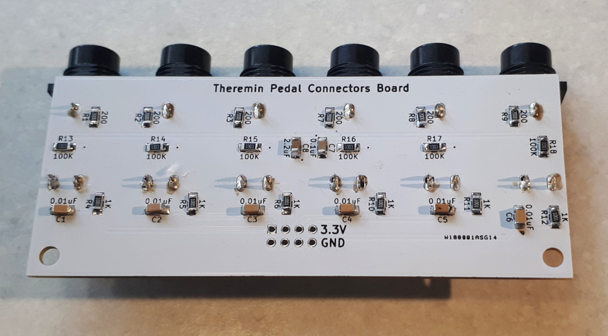
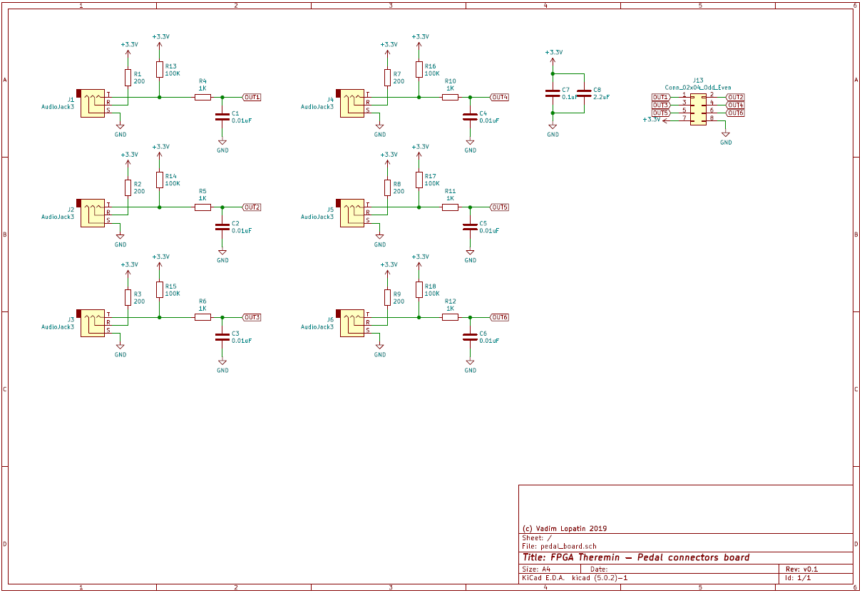
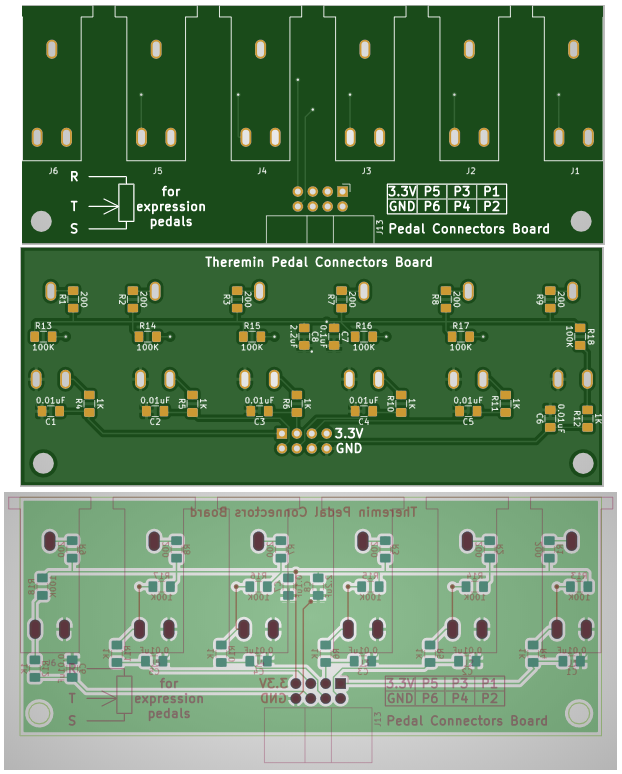
Expression Pedal Connectors
Board with audio jack 6 connectors for expression pedals (potentiometer based) Provides 6 analog inputs to ADC. 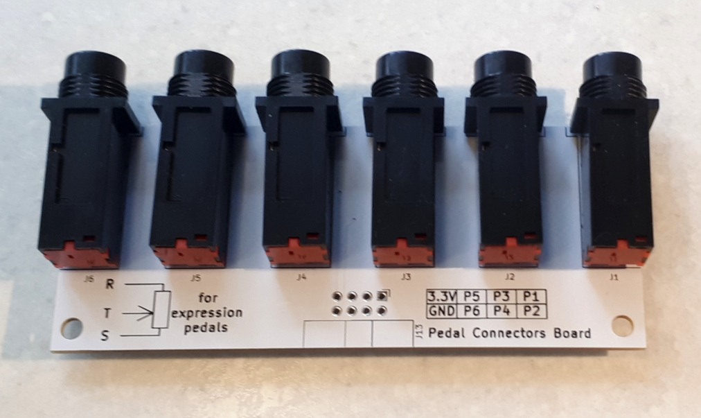
|
 |
|
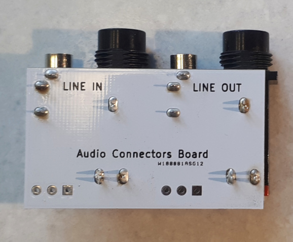
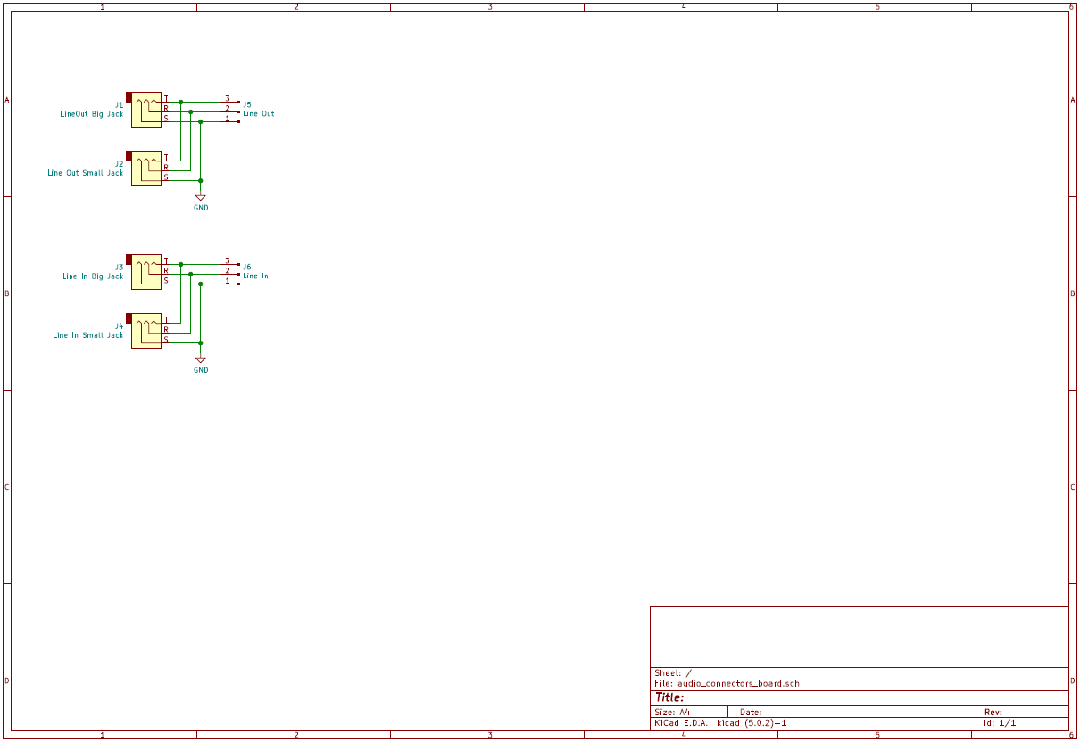
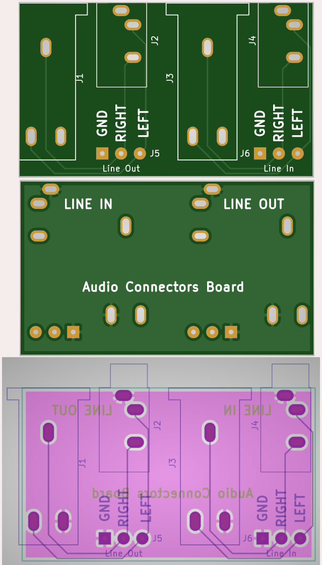
Audio Connectors
Breakout board for mounting of Line In and Line Out 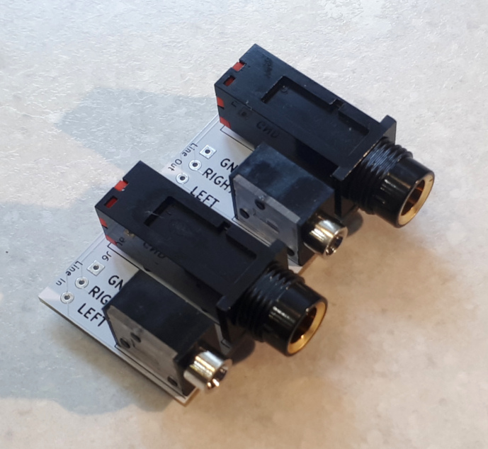
|
 |
|
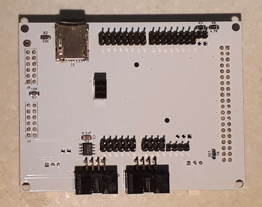
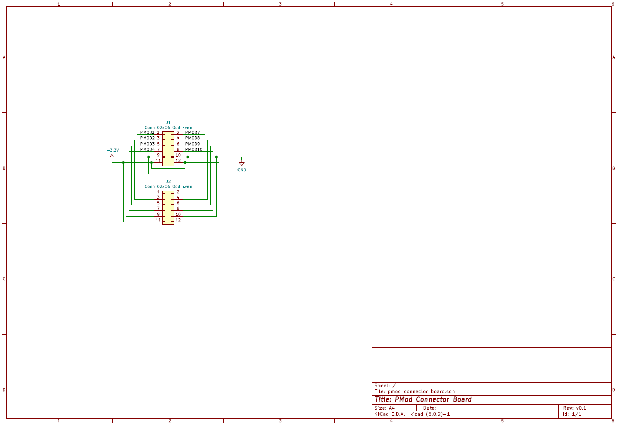
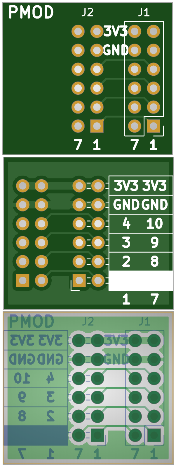
PMod adapter
Used to mount two (I2S2 and AMP3) PMods on top of shield board, leaving on-board PMod ports of Cora Z7 board unused for future extension. 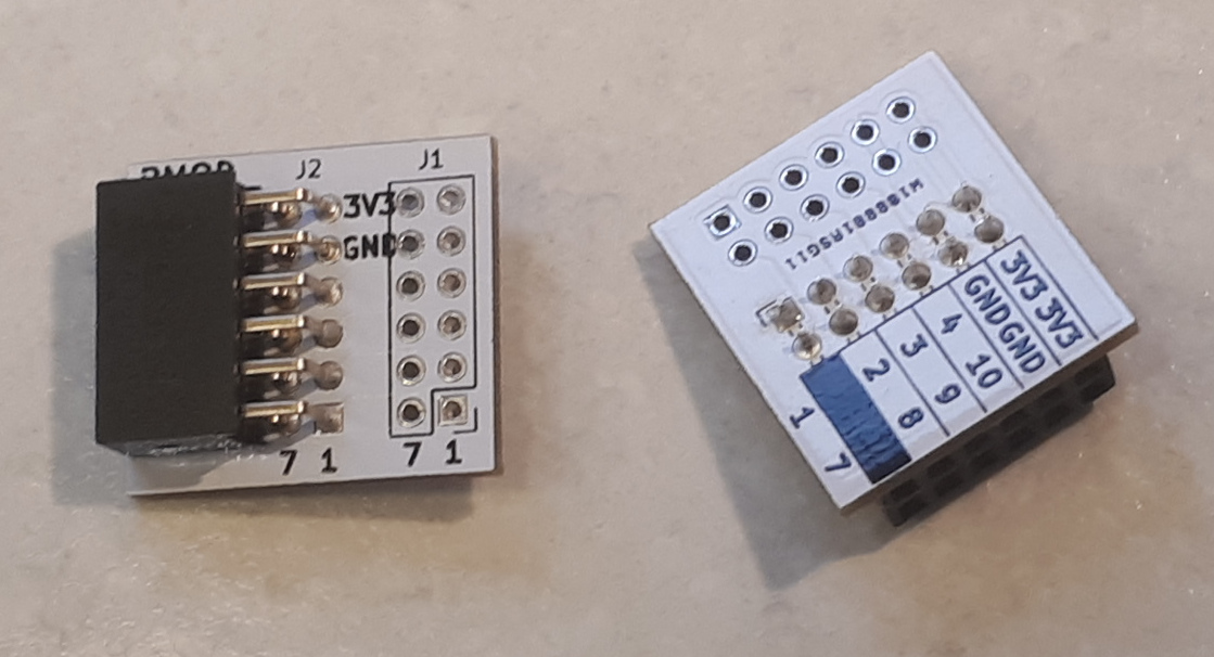
Adapters on shield board with PMods: 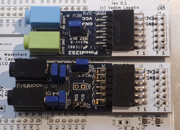
|
 |
|
LCD Mount
|
No schematic. It's just for mounting of Waveshare 4.3inch 800x480 touch LCD | 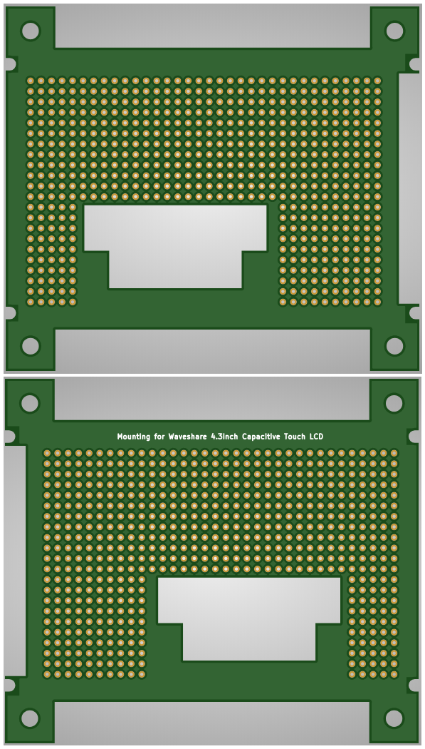
|

Software
This is FPGA PSOC project. Source code consists of two parts: PL (FPGA) and PS (C++ code for ARM core).
Source code is available on GitHub
Design of FPGA IP (SystemVerilog modules) and standalone drivers can be found on separate board related pages